- Liquid Ring Vacuum Pumps
- Single Cone Vacuum Pumps /
Liquid Ring Vacuum Pumps - Close Couple Vacuum Pumps
- Two Stage Vacuum Pumps
- Twin Lobe Roots Blower
- Chemical Process Pump
- Pump Spares Parts
Technical Support
Cavitation in Liquid Ring Vacuum Pumps used in Condenser Venting Service
Kevin Skelton, Graham Corporation, 20 Florence Ave., Batavia , NY 14020
Abstract
Power generating facilities use a Liquid Ring Vacuum Pump (LRVP) to remove air and other non-condensable gases from turbine exhaust surface condensers. Although an LRVP is an accessory to a steam surface condenser, paper performance of the LRVP is critical to condenser operation, and ultimately turbine back-pressure. Performance of an LRVP may be influenced by a number of variables, however this paper will focus on cavitation. Under certain conditions, the LRVP can cavitate causing major damage and a shortened life span for the pump.
A systematic approach was used to study cavitations in an LRVP. To conduct the study, a range of service liquid (water) temperatures and non-condensable gas (air) loads were introduced into the LRVP. The objective was to establish conditions that exist in a cavitations environment and to document the results. A combination of system pressures and service liquid temperatures offer an interesting correlation in the formation of cavitations for this type of pumping system.
This paper discusses the operating characteristics of an LRVP, how cavitations occurs and what to do to eliminate the problem. It concludes with actual case studies which cover system troubleshooting and corrective action required.
Test Appartus And Procedure
The testing was performed in the Research & Development Facility at Graham Corporation, in Batavia NY, using Graham Model 1PV82450/fnz Liquid Ring Vacuum Pump, which is about an 800 ACFM pump at 1" Hg(G) Abs. The test facility utilizes a variable frequency drive and motor with a Daytronic data acquisition system, Model 10. In addition, the company's vast data bank of performance tests was utilized, when necessary, as a means to confirm the operational characteristics of the LRVP used in this service.
The Liquid Ring Vacuum Pump
A Liquid Ring Vacuum Pump consists of a multi-bladed, rotating element (impeller), electricity positioned within a cylindrical casing. The compression of the gas occurs in one or two impeller stages depending on the ultimate vacuum required, although for this service two stage pumps are generally required. Water or some other incompressible fluid, called service liquid, is introduced to the LRVP. As the impeller rotates, a ring of liquid is formed inside the pump casing from centrifugal force. This action draws the gaseous stream into the pump through the inlet port. The gas is compressed by the liquid ring, exiting the first stage through a smaller area discharge port and into the second stage of the pump. The second stage is volumetrically smaller doing the final compression of the gas. The gas then exits the pump usually at atmospheric pressure, along with the service liquid. See Figure 1.
Since the service liquid actually does the compressing area of the gas, its' specific characteristics are important, with the heat capacity (specific that) and the boiling point (vapor pressure) being two of the most important. Other factors such as the solubility of process components into the service liquid and service liquid viscosity must also be considered.
From a utility usage standpoint, the LRVP is an alternative to the steam jet ejector for venting turbine exhaust surface condensers in power producing applications. It is important to understand that the surface condenser produces the vacuum, not the LRVP. In other applications, the LRVP will produce a vacuum on a closed vessel, but in this application, the LRVP is designed to operate at the same vacuum (pressure) level as the condenser, it supports condenser operation by continually extracting the non-condensable gases (air) that enter the condenser. This maximizes the condensing capability of the condenser and minimizes turbine exhaust back pressure.
Cavitation
Cavitation is a phenomenon which occurs in specific fluid environments and is an important factor when using this type of vacuum equipment. Vapor bubbles, like boiling water, form in the fluid at a specific pressure and temperature.
For example, at atmospheric pressure, water boils 212 0 F, while at a lower pressure (vacuum) it will boil at a lower temperature, {i.e., at 52 mmHgA (27.87" Hg(G) vacuum), water boils 102 0 F}. Conversely, as the pressure is increases, water will not boil until it reaches a higher temperature, like in a pressure cooker. The Steam Tables are referenced to determine the vapor pressure of water at various temperatures.
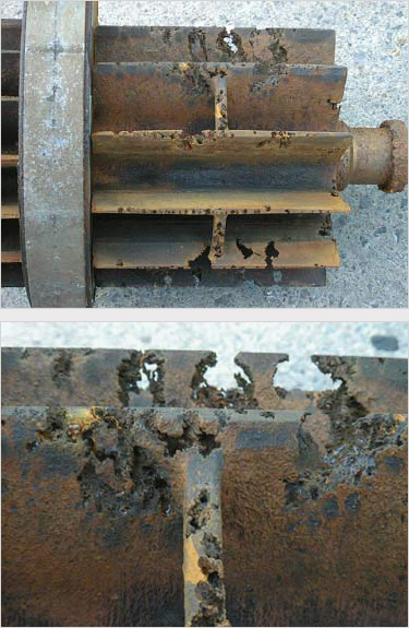
Examining the internal components of an LRVP reveals many areas which can be damaged from cavitation. The damage is recognized as a series of craters or holes in a continuous pattern on an LRVP impeller. The damage can occur on either impeller stage depending on specific conditions. Also, damage can occur on the suction and discharge ports in either stage of the LRVP.
To control or prevent cavitation, the service liquid must be able to support the vacuum level established in the condenser without boiling or vaporizing. The vaporization of the service liquid sets up the structures of cavitation in the LRVP, but the damage is caused when the vapor bubbles collapse, not when they form. When the collapse occurs, a high velocity micro-jet of water tears away at the metallic surfaces of the pump internals.
In order for the collapse of a vapor bubble to occur, there must be an increase in pressure or a decrease in temperature in that area of the pump, once the vaporization has taken place. A pressure increase is expected, occurring as the gas is compressed while passing through the pump and out of the discharge. Therefore, in order to keep the pump from cavitation, the temperature of the water must remain below the saturation point corresponding to the inlet pressure. The service liquid must be cold enough to avoid vaporization at the lowest anticipated pump operating pressure. Once vaporization occurs at a lower pressure, a collapse is inevitable, as the gas is compressed to a higher pressure.
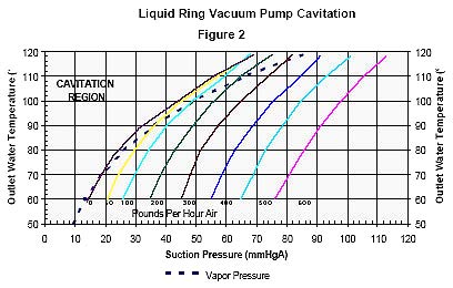
Figure 2 shows the dry air handling capacity, in pounds per hour (PPH), of the LRVP utilized in this study. The Outlet Water Temperature in 0 F is plotted as a function of the Pump Suction Pressure in mm Hg(G) Absolute (mmHgA). The vapor pressure of water is also plotted to illustrate where the pump crosses into the region when vaporization will occur. It is important to point out that the outlet water temperature of the LRVP is used on this graph since it is what ultimately regulates the pump suction pressure.
Some interesting performance results are documented on this graph. First, it is shown that an LRVP can operate blanked-off (no-load), without cavitation, if the water temperature will support the vacuum. The suction pressure of the pump varies as a function of the outlet water temperature. As the graph illustrates for the same non-load condition, the suction pressure rises as the water temperature rises. This actually illustrates how the capacity of an LRVP is affected by the temperature of the water or service liquid.
The problems that occur when the temperature of the water changes the LRVP's capacity will be discussed later.
Referring to the graph, if the outlet water temperature stays below 700 F, the achievable suction pressure is 18 mmHgA which is close to the partial pressure of water at this temperature. But, if the outlet water temperature increases to 800 F, the suction pressure increases to about 25 mmHgA. The partial pressure of 800 F water is 26.21 mmHgA, so the pump is cavitating at this particular condition. The graph shows how the region of cavitation increases as the outlet water temperature increases. The LRVP cannot operate at non-load, without cavitation in this region.
Cavitation in an LRVP can usually be attributed to a change of initial system conditions. The graph shows how a pump can operate in a safe region and then be carried into a cavitation region merely from a change in the water temperature. The only difference in the system is that the water temperature has increased.
The graph also shows how the service liquid vaporizes in the pump under specific operating conditions. The location of cavitation damage in the pump can also vary, as anyone who has examined pump internals will asset. Depending on the initial temperature conditions and the load being handled by the pump, cavitation can occur anywhere, not just in the first stage where the lowest pressure exists.
To prevent cavitation in the LRVP, the cause of the temperature rise must be determined. Even though the operation of an LRVP can be considered aloes to isothermal (constant temperature), a rise in the water temperature occurs for various reasons. Temperature rise occurs due to absorption of the heat of compression from the horsepower energy into the water. Also, the condensable component of the inlet load to the LRVP rejects heat into the water as it changes phase. Lastly, the non-condensable portion of the inlet load stream will reach an equilibrium temperature with the water, also rejecting heat. Any or all of these sources of energy, attribute to the rise of the water temperature in the LRVO. The quantity of service liquid entering the pump is important to maintain because of the requirement to keep the outlet water temperature below the saturation temperature corresponding to the suction pressure of the LRVP.
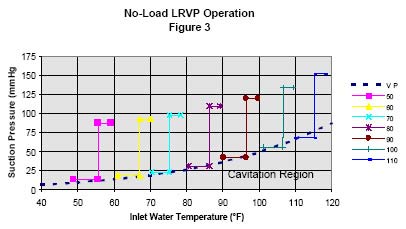
The illustration on how cavitation damage can occur anywhere throughout the LRVP is shown in Figure 3. The graph shows a series of inlet water temperatures plotted with suction pressure as a function of the water temperature. Again, the vapor pressure curve for water is plotted to complete the analysis on this graph. Each set of lines show the temperature and pressure that was measured in each stage of the LRVP for a given initial water temperature. The lower horizontal portion of each line shows the temperature rise in the first stage, while the vertical line illustrates the rise in pressure from the first stage to the second stage for a given temperature. The upper horizontal line which is shorter, signifies the temperature rise in the second stage. For simplification purposes, the pressure shown in each stage is shown as being constant for the rise in temperature. This is actual, if you consider that the pressure in each individual impeller bucket is constant, but increasing as the impeller rotates. The testing proved that the water temperature increased along the length of the pump.
The graph also shows that colder water keeps the operation of the LRVP out of the cavitation region and as the water gets warmer more of the first stage impeller enters the cavitation region. This linear relationship can be used to illustrate how cavitation can occur anywhere in the pump. If more of the first stage horizontal line is in the cavitation region, more of the overall pump will be subject to cavitation.
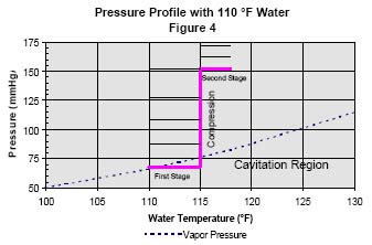
A close up of the most extreme case tested is shown in Figure 4. For the 1100 F water case, most of the first stage impeller is in the cavitation region. As the impeller rotates and the gas is compressed to the inter-stage pressure, the collapse occurs on this area of the impeller. The translation from the first stage to the second and the second to the exit of the pump is illustrated by the dashed lines on the graph.
Condenser Operation
Over-venting of the condenser is caused when the LRVP operates at a lower pressure than the condenser. This results in condensable load being drawn from the condenser into the pump in addition to the existing non-condensable load. The condenser operates at one pressure, established by its cooling water and the LRVP is able to operate at a lower pressure because its water is colder. The LRVP is now operating as a direct contact condenser. The latent heat from the condensable load is rejected into the service liquid which adds to the temperature rise across the pump and may cause the pump to cavitate. The LRVP should always operate in conjunction with the condenser. To do this, the cooling water to the service liquid heat exchanger on the LRVP system and the condenser water must be the same temperature. Also, the physical characteristics of each heat transfer device must be the same. It is assumed that the original design of each, has permitted this to be possible. In actual operation, each device must be maintained properly to maintain this integrity.
Under-venting of the condenser is caused when the LRVP cannot remove the non-condensable load entering the condenser. The condenser pressure will rise and turbine operation is affected. Under-venting is normally the more visible problem and is usually corrected by starting an additional LRVP in an attempt to lower the condenser pressure. If the temperature of the water in the LRVP will not allow the pump to operate at the same pressure as the condenser, cavitation will occur in LRVP. Starting an additional LRVP at this time will result in two pumps cavitating instead of one.
Another feature used by some condenser exhauster suppliers is a direct contact water spray introduced at/ or near the LRVP inlet. Unless the temperature of the water is lower than the saturation temperature corresponding to the suction pressure of the pump, no condensing or volume reduction of the load stream will occur.
The Service Liquid Heat Exhanger
The main culprit in a problematic LRVP system is the service liquid heat exchanger. This heat exchanger, normally referred to as a seal cooler is used on LRVP systems where the service liquid is reused after it exits the LRVP. The service liquid is cooled to a lower temperature, so the desired vacuum and capacity of the LRVP can occur. The cooler is often overlooked when the LRVP system is maintained.
The proper heat transfer function of this heat exchanger is essential for trouble-free vacuum system operation. If the correct heat transfer between the two fluids is not taking place, the LRVP will operate in a different pressure range than the condenser. As started previously, the condenser and the LRVP must operate in conjunction with one another using similar water temperatures.
The service liquid heat exchanger may have to be cleaned to maintain its heat transfer capability. First check to ensure that the proper flow and temperature of cooling water is being supplied to the heat exchanger. Next, measure the temperature change across both sides of the heat exchanger, confirming the results with the original design information. If the temperature rise is low on the cooling water side and the water is not cold enough on the service liquid side, fouling could be the problem. Also ensure that there is no place for air to accumulate inside the exchanger reducing its heat transfer surface. All too often the cooling system never worked as intended. The heat exchanger could be under-sized or the original design criteria may be different than the actual operating conditions. It is also possible that the heat exchanger become fouled immediately upon system start-up, due to improper system flushing. It is critical that the service liquid cooler be cleaned at regular intervals and should be as closely as the main condenser for proper operation.
Once the water temperature issue has been cleared up, problems can still occur if the non-condensable load from the condenser is less than the capacity of the pump at the specific water temperature being used. The LRVP is a fixed volume machine which will satisfy its requirement with load either from the condenser or from its own service liquid. Since the suction pressure of the LRVP will vary as a function of the water temperature, it is very possible that the load from the condenser will affect its operation. If the air load from the condenser is less than expected, the LRVP will attempt to operate in a lower pressure range. If the water temperature in the LRVP is higher than the condenser water, the pump will cavitate. Typically a vacuum relief valve is supplied to prevent cavitation by adding air load to the LRVP. The vacuum relief valve should only be adjusted after it has been determined that the service liquid temperature into and out of the LRVP is correct.
Cavitation Cause Checklist
- Is the service liquid temperature into the LRVP low enough to support the desired vacuum?
- Is the service liquid temperature out of the LRVP low enough to support the desired vacuum? (Refer to the Steam Tables)
- Is the flow of service liquid to the LRVP sufficient to minimize temperature rise?
- Is the service liquid heat exchanger plugged, fouled or air-bound ?
- Is the cooling water to the heat exchanger cold enough to provide the correct LRVP inlet water temperature?
- Is the vacuum relief valve adjusted properly to provide sufficient air load to the LRVP to prevent convitation?